Nach dem Bau der MantaEvo möchte ich nun die Entwicklung der Stardust weiter dokumentieren.
Ausgehend von einem NACA – Profil 16-012 für das Unterwasser hat Hammax einen interessanten Vorschlag im RG Forum mittels Freecad präsentiert, den ich als Grundlage für die Stardust verwende. Den Bug habe ich noch etwas über die Wasserlinie gehoben, um die benetzte Fläche weiter zu reduzieren. Die Resultate des Unterwasser mit den Formkoeffizienten siehe hier.
Die gesamte CAD Konstruktion inkl. aller Einbauteile erfolgte in Freecad. Mit dem Prusa Slicer und dem Hevo 3 D Drucker wurden alle Teile mit PETG blau metallic von Extrudr hergestellt. Details siehe Beitrag MantaEvo.
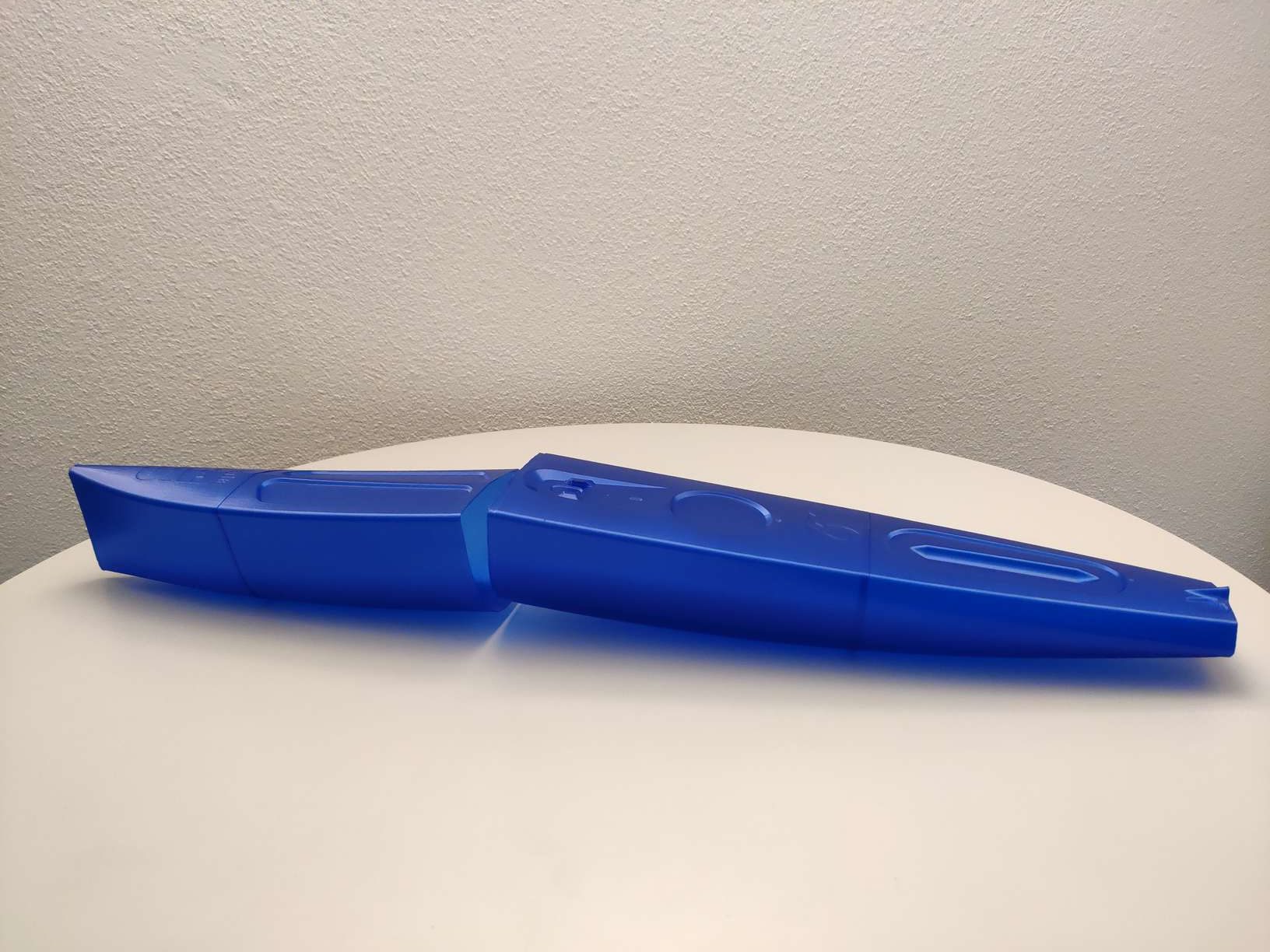
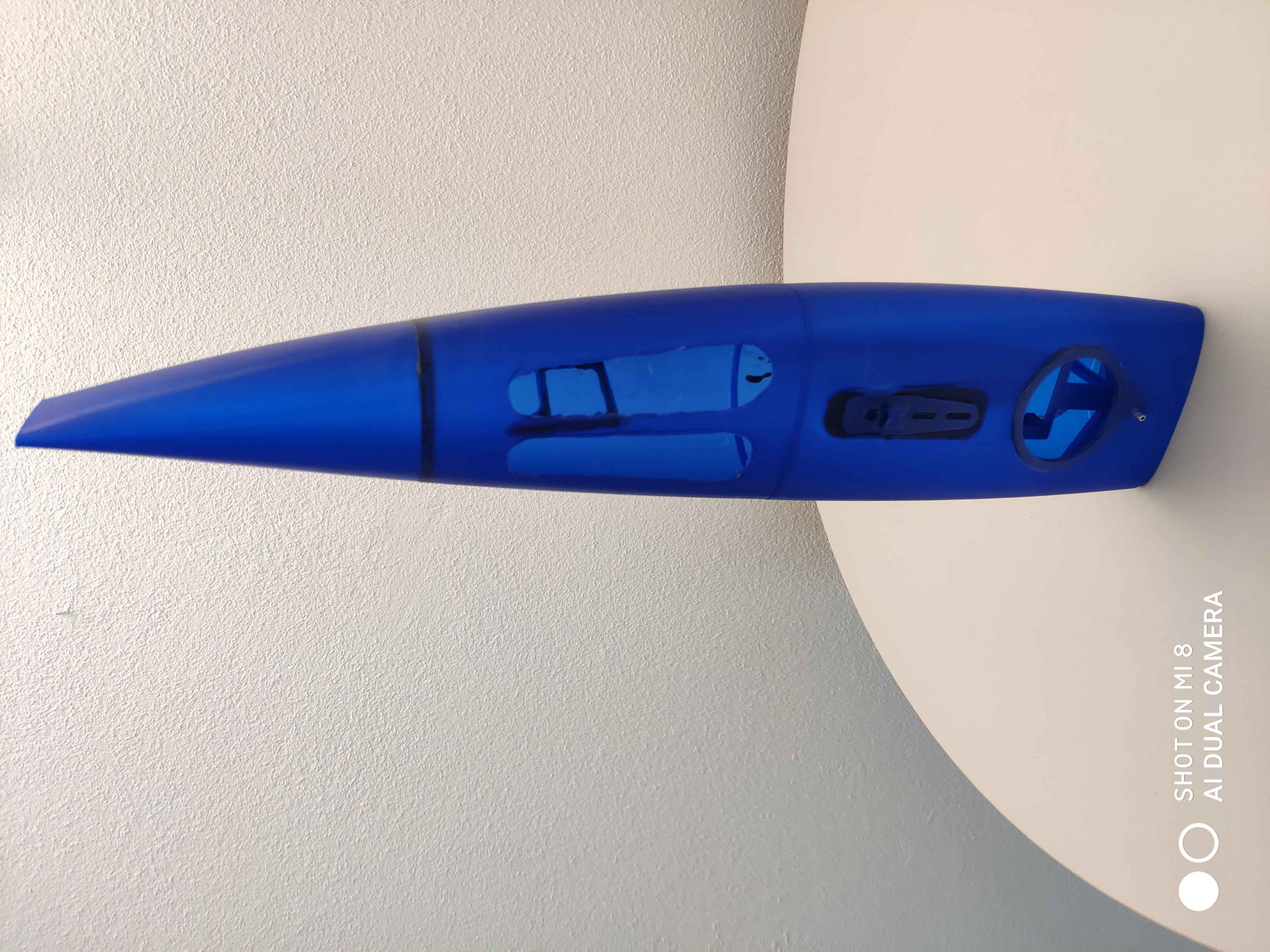
Die Stardust Sektionen fertig aus dem 3 D Print!
Gesamte verwendte Elektronik inkl PETG Bauteile:
Frsky Empfänger RX6R (RX4R hätte auch gereicht!)
Hitec MD250MW und D-Power HVS 228 MG HV als Servo und 850mah LiPo
Accuhalterung und Sheetführung
Mastteil komplett mit Schwertkasten und Accu-Sheet
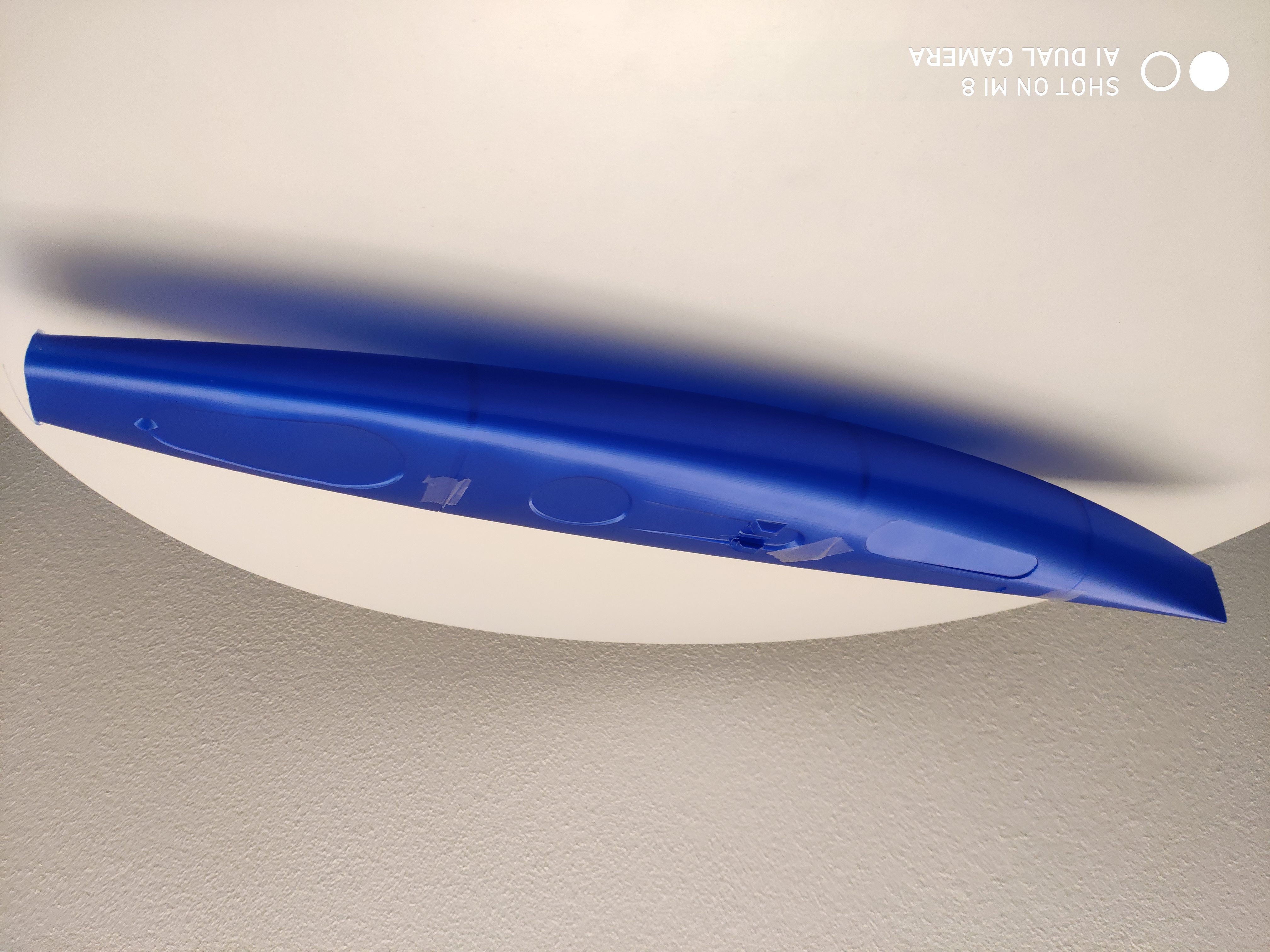
Heckteil mit Ruderkoker komplett verklebt!
Foto von der fertigen Stardust folgt!
Stapellauf bei wenig Wind – Das Boot ist dicht und reagiert sensibel auf Steuerbefehle.
Lässt sich leicht wenden und beschleunigt bei kleinstem Windhauch.
Erste Eindrücke siehe Video.
Das Boot ist schnell -> Training auf dem Heidsee
Seit einigen Jahren treffen sich die Modellsegler zu einer internationalen Regatta auf dem Heidsee in der Lenzerheide. Als aktiver Laserregattasegler und Technikbegeisterter faszinierte mich dieser Sport schon immer. Warum also nicht von der langsam zu Ende gehenden Laserregatterei (Alter) zum Modellsegeln umsteigen? Ein funktionierender Sender von der Drohnenfliegerei hatte ich ja bereits. (Siehe vorgehende Artikel). Als Einsteiger war es deshalb einfach mal eine segelfertige DF65 im Ricardo zu ersteigern und an einer Regatta teilzunehmen. Gegen die RG65 im Teilnehmerfeld hatte ich mit meinem A Rig natürlich keine Chance. Also befasste ich mich mit diesen RG65 Klasse intensiver und stiess dabei auf die Neuentwicklungen im 3 D Druck.
Bau eines 3 D Druckers
Nach eingehendem Studium der verschiedene Drucksysteme entschied ich mich keinen billigen «Bettschubser» zu bauen, da die dünnwandigen Bootsschalen stabil auf dem Drucktisch entstehen sollen und dazu eignete sich das CoreXY-System m.M. am besten. Fertige Bausätze sind in China einfach erhältlich werden dann aber von den Makern meist schnell modifiziert. Im Facebook fand ich eine deutsche Arbeitsgruppe die unter super Anleitung den Bau eines Hevo unterstützt. Der HEVO, wie der Hypercube Evolution unter Insidern genannt wird, folgt der CoreXY – Philosophie mit einer Standard-Druckbettgröße von 300x300x300mm. Dennoch ist er extrem modular und erweiterbar aufgebaut und kann nach Bedarf vergrößert oder verkleinert werden (700x700x700mm und mehr möglich). Die bestehende Stückliste modifizierte ich mit den Tips aus der Arbeitsgruppe. Für den Aufbau des Hevo folgte ich den Anweisungen in der Video Serie. Mein Hevo habe ich mit altem 600W BeQuiet PC Netzteil ausgerüstet d.h. es ist ein 12 Volt System. Das Duet2 Maestro wird mit einem Noctua Lüfter gekühlt so bleibt die ganze Steuerung im Gehäuse um die 30°C.
Hevo im Rohbau
Die 6 mm Alu Heizplatte hat mit dem 12 V System etwas länger zum Aufheizen auf z.B. 80°C. Würde ich heute bei neuem System in 24 V bauen! Da ich meistens mit PETG drucke hat sich die Kaptonfolie auf der Alu Platte hervorragend bewährt, für PLA dagegen ist sie ungeeignet! Als Druckbett Sensor verwende ich das Precision Piezo Orion Z-probe Kit. Video: Hevo an der Arbeit!
Im Video sieht man sehr schön, wenn das schmale Druckteil am Boden keine Umrandung hat ist die Stabilität nicht gewährleistet. In der Zwischenzeit mache ich 8 Schleifen als Umrandung!
Die Bedienung des Hevo erfolgt via Webbrowser und ist sehr übersichtlich aufgebaut.
Das Duet2 Maestro hat einen Webserver mit dem man die ganze Konfiguration bequem am PC einstellen kann.
Filamentlade/Entlade Scripts etc. können so einfach per Makro erstellt werden.
Alles in allem ein gelungener 3D Drucker der alle meine Wünsche erfüllt!
Slicer
Ich habe verschiedene Slicer ausprobiert Cura, Ideamaker und schliesslich bin ich beim Prusa gelandet. Wichtig ist, dass man damit ein optimales Resultat erhält.
Für die Bootschalen verwende ich eine 0.4mm Düse im Vase Modus (Spiral) mit einer Wandstärke 0.60mm und Schichthöhe 0.15mm.
Zubehörteile drucke ich mit der Konfiguration 15% 3D-Bienenwabe-Infill und 3 Boden und 3 Deckflächen, was sehr stabile Teile mit schönen Oberflächen ergibt.
Filament: PETG 1.75mm von Extrudr verarbeite ich mit 230°C und 80°C Heizbett. (Parameter abhängig vom Hersteller und Hotend)
CAD
Als Linux Anwender kommt das im Modellbootdesign oft verwendete Fusion360 nicht in Frage, weshalb ich mich gleich mit Freecad befasste.
Der Einstieg ist etwas komplex aber die Möglichkeiten sind unendlich. Hier ein Beispiel wie ich mich mit den Kollegen im Freecad Forum schnell einarbeiten konnte.
Natürlich wollte ich auch gleich ein eigenes Design “Stardust” entwickeln.
Erste Berechnungen über benetze Fläche, Schwerpunkt etc. sind im MakroInfo möglich.
Im Moment ist das Stardust Projekt auf Eis gelegt und ich werde das nun folgende Boot von Andy Hoffmann die Manta Evo Swing Edition 040 vorstellen. Das Design kann man bei Andy anfragen.
RG65 Manta Evo
Andy Hoffmann ist ein erfolgreicher RG65 und IOM Modellbausegler und konstruiert seit vielen Jahren erfolgreiche Boote. Seine neueste Entwicklung die Manta Evo werde ich nun hier versuchen aufzubauen.
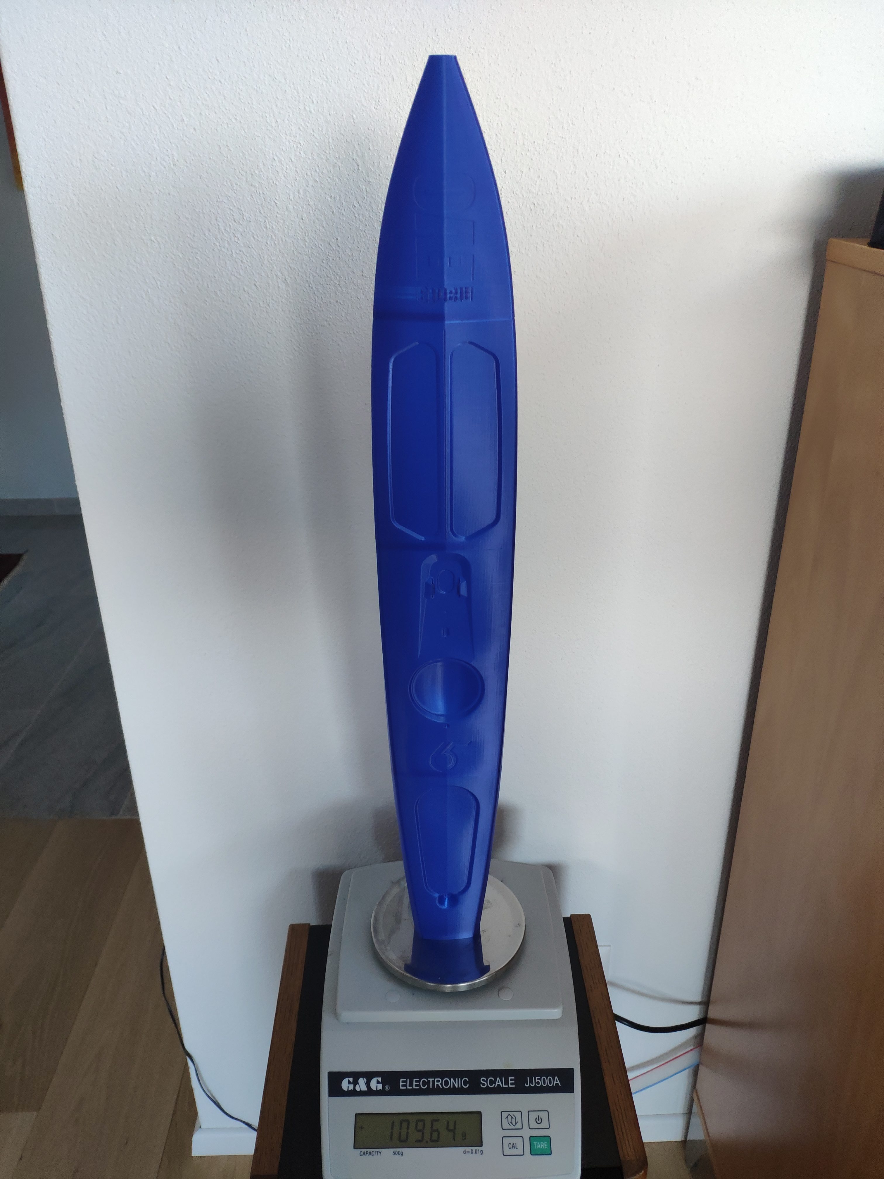
Als erstes druckte ich die 4 Hullsegmente in PETG und ich glaube die sind gut gelungen: Version 032!!
Version 040:
Das Gewicht von 110 gr für die unbearbeiteten Segmente ist ok.
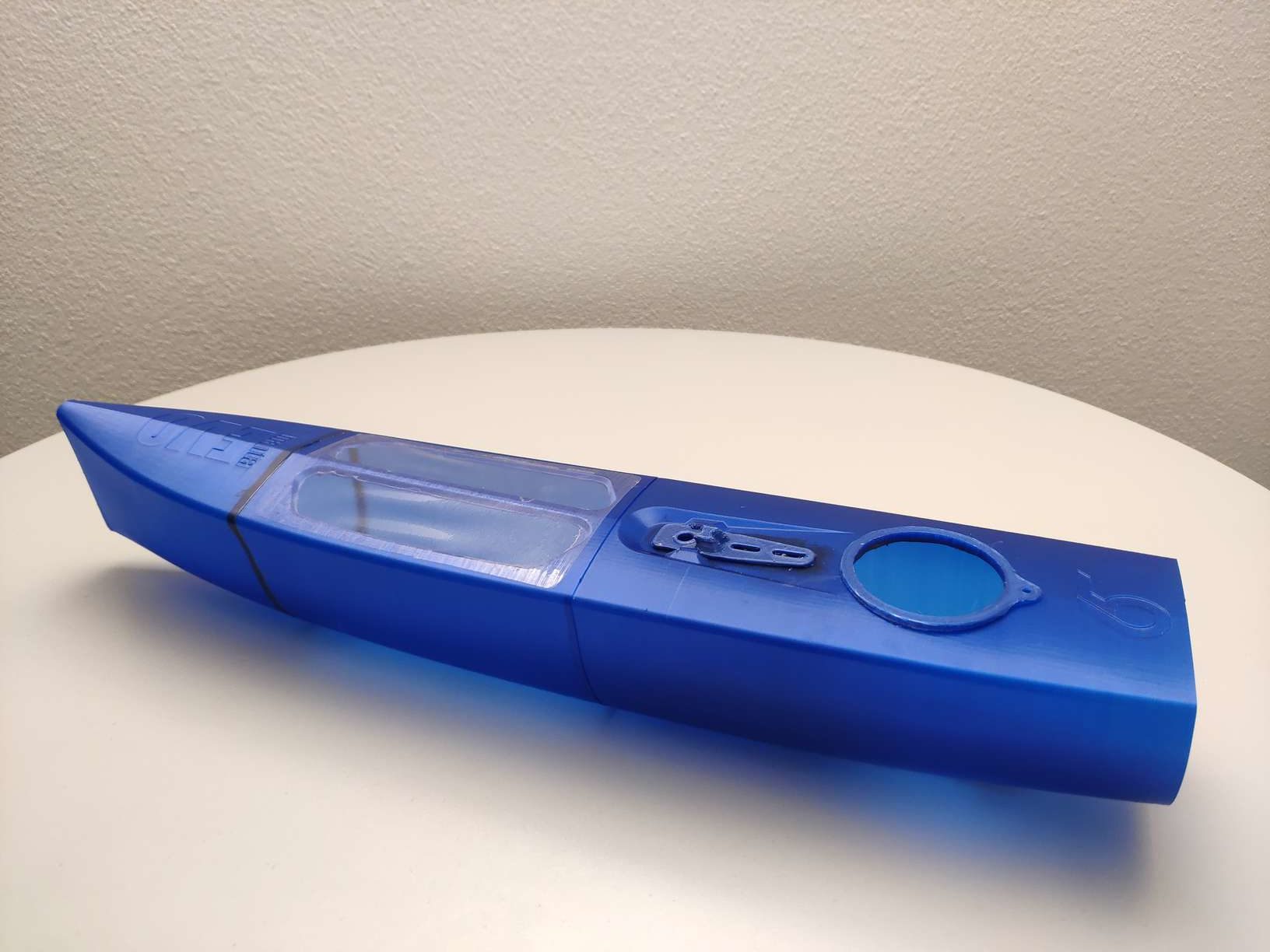
Jedes Element hat eine Fase, die das Zusammenstecken und Verkleben vereinfacht.
Der 2 Komponenten Kleber 3M SW 2216 Scotch Weld 2 K flexibel eignet sich hervorragend, da er eine lange Topfzeit (90 Min) hat und sich durch extrem hohe Schälwerte auszeichnet! Leider ist er dunkelgrau und eignet sich nur wenn das Boot später lackiert wird. Alternativ habe ich UHU 3000 und Pattex XXXXXXX verwendet, wenn die Farbe stört. Im Vorschiff wird nun der Servo Hitec D89MW mit Halterung verklebt. Der Ruderservo D-Power HVS-228BB MG mit dem Ruderkoker wird komplett ins Heckteil eingeschoben und ebenfalls verklebt.
Als Empfänger setze ich den Frsky RX4R ein. Ein 2S Lipo mit 850mAh wird mit Velcro hinter der Keelbox befestigt.
Nachdem alles verklebt ist folgt der Wasserdichtigkeitstest. Scheint soweit gut zu sein.
Die nächste Herausforderung mit dem Rohling eine Vergleichsregatta zu segeln, um die Wettbewerbsfähigkeit zu messen. Je nachdem wird dann die Manta noch geschliffen und lackiert.
Zielsetzung Einen möglichst leichten Quadrocopter zu bauen, der lange Flugzeiten erlaubt, deshalb verwende ich für dieses Projekt möglichst keine Metallbauteile und ersetze sie mit Carbonstrukturen die verklebt werden.
Beschreibung
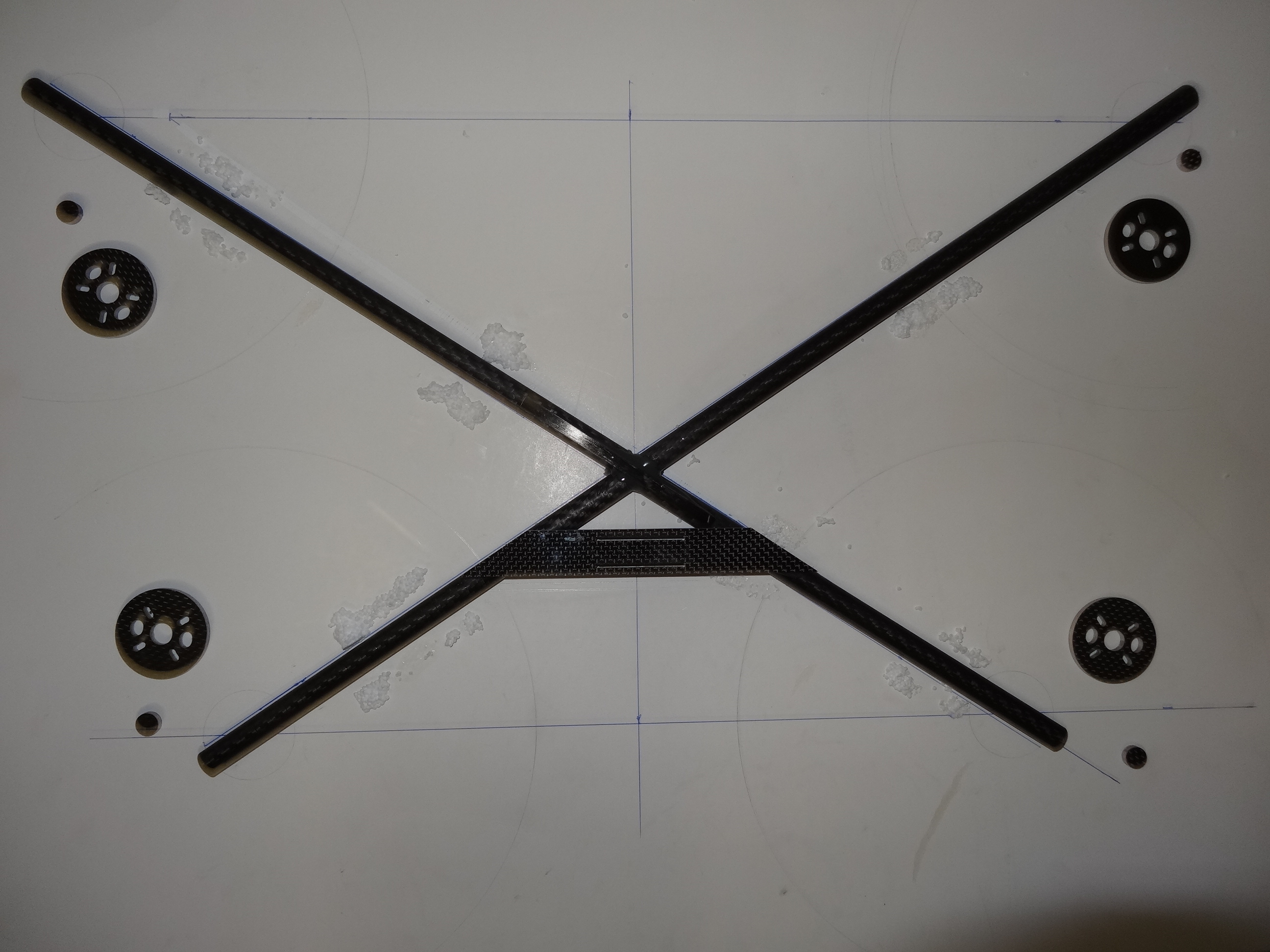
Das Frame besteht aus 12 mm Carbontubes. (Sanded Roll Wrapped Twill Carbon Fabric Tubes) mit 1 mm Wandstärke. > 50gr/m
Das asymmetrische Design mit grösserem Öffnungswinkel für die Kamera wurde mit Cad Design entworfen (MyQuad) Quelle Forest Frantz.
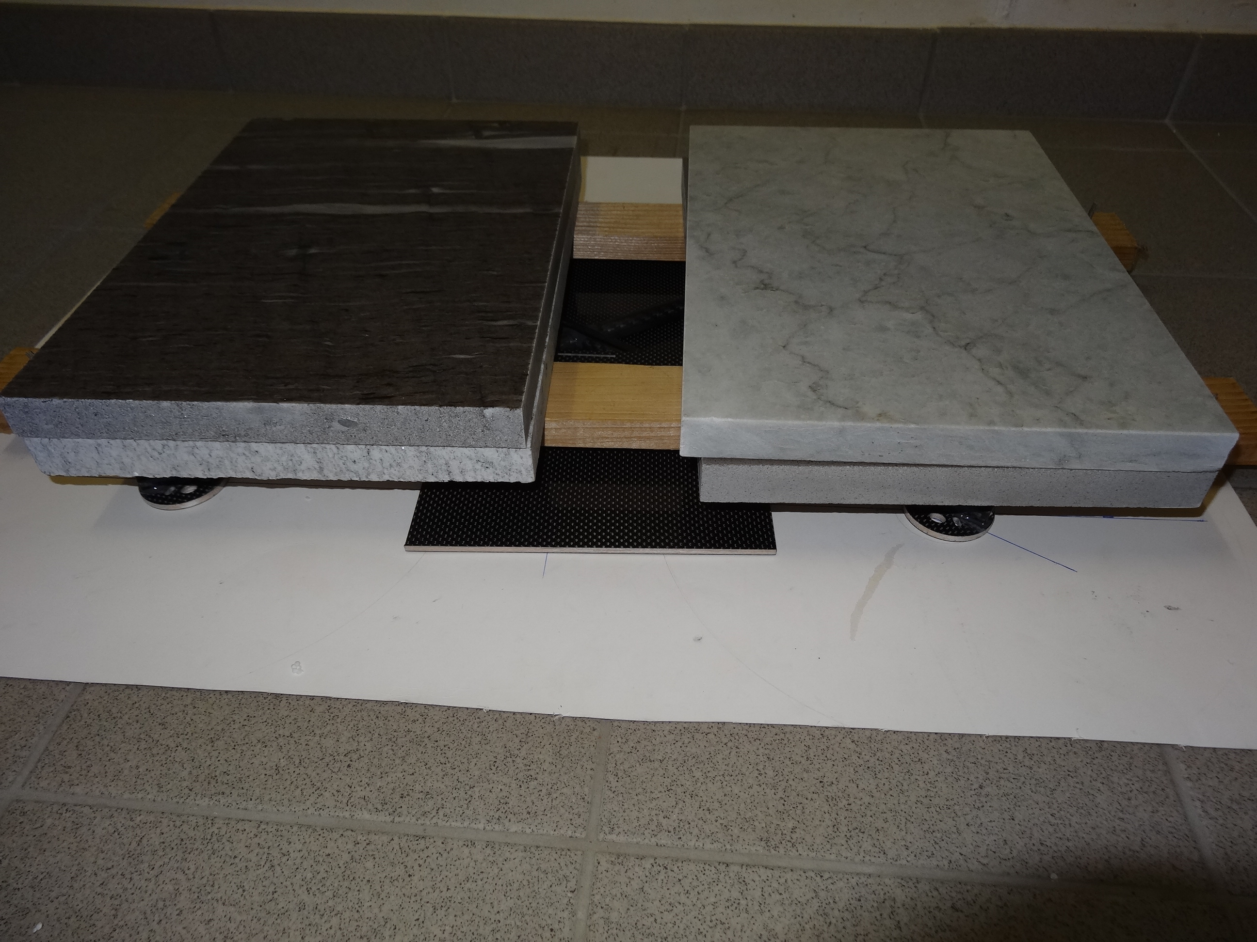
Die Motoren werden mit Nylon M3 Schrauben auf Carbon Balsa Sandwich befestigt. Dies ergibt bei einem Crash eine sogenannte Sollbruchstelle und soll die Carbonstruktur vor einem Bruch schützen. Sämtliche Carbon Balsa Sandwich werden auf die Carbon Tubes geklebt (siehe Bild). Diese Teile konnte ich bei einem Spezialisten problemlos in kürzester Zeit herstellen. (Keiro). Der 2 Komponenten Kleber 3M SW 2216 Scotch Weld 2 K flexibel eignet sich hervorragend, da er eine lange Topfzeit (90 Min) hat und sich durch extrem hohe Schälwerte auszeichnet!
Gewicht des Carbon Frames:
Landegestell mit halben Carbon Lauffahrwerken:
Der fertige Quad:
Mittlerer Weile fliegt diese Drohne erfolgreich mit einer SJ4000 Camera und einem einachsigen Gimbal problemlos. Der Fixhawk fliegt im Moment mit Ardupilot 3.6.9.
Alte Festplatte mit Live Medium in Gparted reduzieren, so das System auf der kleineren Platte Platz hat. Die kleinere Festplatte gleich aufteilen wie die alte Festplatte.
Die Festplattenbezeichnungen ermitteln:
sudo fdisk -l
z.B. alte Festplatte /dev/sda1 für Wurzelverzeichnis / und neue SSD /dev/sdb1
und /dev/sda2 als Home /home und neu auf SSD /dev/sdb2
Diese Partitionen unter LiveCD einbinden:
sudo mkdir /mnt/alt
sudo mount -o ro /dev/sda1 /mnt/alt (Read only gemountet)
sudo mkdir /mnt/neu
sudo mount /dev/sdb1 /mnt/neu
Daten mit rsync kopieren ist besser und schneller als mit dd!
sudo rsync –stats –progress –numeric-ids axAhHSP /mnt/alt /mnt/neu
Falls man nachher sicherstellen will das Kopie vollständig ist kann man mit Option -c vergleichen:
sudo rsync –stats –progress –numeric-ids axAhHSPc /mnt/alt /mnt/neu
Die Partitions wieder aushängen:
umount /dev/sda1
umount /dev/sdb1
Nun das gleiche mit der Home Partition machen:
sudo mount -o ro /dev/sda2 /mnt/alt (Read only gemountet)
sudo mount /dev/sdb2 /mnt/neu
sudo rsync –stats –progress –numeric-ids axAhHSP /mnt/alt /mnt/neu
sudo rsync –stats –progress –numeric-ids axAhHSPc /mnt/alt /mnt/neu
umount /dev/sda2
umount /dev/sdb2
Je nach Grösse der Partitions sind 1-2 Stunden einzuberechnen für diese Operationen!
Als nächstes kann man die alte Festplatte ausbauen.
Die LiveCD starten mit der neuen SSD. Nun muss noch überprüft werden, ob die fstab Datei angepasst werden muss.
sudo blkid
zeigt alle UUID an die dann für sda1 und sda2 notiert werden.
Jetzt noch Grub auf der neuen Platte installieren und evtl die fstab Datei ändern:
sudo mount /dev/sda1 /mnt
weiter:
sudo mount -o bind /dev /mnt/dev
sudo mount -o bind /sys /mnt/sys
sudo mount -t proc /proc /mnt/proc
Jetzt chrooten:
sudo chroot /mnt
Es kommt ein #/ prompt.
grub-install /dev/sda
update-grub
Then exit the chroot:
exit
Ein Quadrocopter ist ein Fluggerät, welches den Auftrieb über vier in eine Ebene angeordnete Rotoren erzeugt. Hier wird der Selbstbau eines solchen Multicopters beschrieben.
Mission Planner is free, open source software available for Windows. These instructions will guide you through installing Mission Planner on your ground station computer.
As part of first time setup, you’ll need to configure some required hardware components using the Mission Planner. These instructions describe the process for selecting frame orientation and configuring the RC transmitter/receiver, compass, and accelerometer.
Because the next steps in this blog involve connecting to the Receiver, you need to turn off power to the ArduFlyer 2.5 board.
In Mission Planner, click Disconnect.
Disconnect the USB cable from ArduFlyer 2.5
I need to correct an error above, it is 5V +/- 5%, NOT 10%
You use one 3 pin cable from one of the headers to connect 5v power and GND to the receiver thus the board supplies power to the receiver
It does NOT matter which channel you use a 3 wire cable on since all the channels on the board can supply power.
The third wire, the Signal wire on that channel connects that channel signal.
The rest of the channels you may use ONLY require the SIGNAL wire to be connected.
There is no need to have a GND and supply wire connected to every channel as that makes the wiring stiffer, cumbersome and more likely to transfer vibration between the receiver and the vibration isolated board.
I use a Spektrum radio so that is what I will be illustrating here, the same principle applies no matter which receiver type you may be using.
Single Signal wires from the first 7 channels connected the last channel which decided to use a 3 wire cable to supply power to the receiver has not been connected yet.
The channel assignment on the Input headers.
Channel 1 is nearest the Alive LED, the white cable in the photo above
Here is how the green bars should move for each channel:
CH 1: Roll/Aileron
CH 2: Pitch/Elevator
CH 3: Throttle
CH 4: Yaw/Rudder
CH 5: Flight Mode Switch
– Radio Calibration –
Connect USB cable from PC to ArduFlyer 2.5 board
Your receiver must be BOUND to your Radio, refer to the instructions that came with your receiver and Radio to perform BINDING
Switch on Your Radio transmitter, check that the Receiver Bind light is turned ON, if not you have to bind the receiver to the radio.
Run Mission Planner
Select correct COM Port, make sure BAUD is set to 115200
Click on the ConfigurationTab
On the left Click on Radio Calibration TAB
Click on Calibrate Radio, read the message then click OK, read the message then click OK
Move each Joystick to all the 4 corners, operate all switches and sliders.
Ideally the range of movement should be between 1000 and 2000, if it is a long way from that you need to adjust your Radio Travel oe End Points, refer to the instructions that came with your Radio.
Check that the correct green bar moves for each joystick, if a different bar moves, that means you have your radio channel connection between the Receiver and ArduFlyer 2.5 connected incorrectly, switch your cables around to correct the situation.
Check that the green bars all move in the correct direction as detailed below
NOTE: Pitch is backward to the way you would expect it to be
Here is how the green bars should move for each channel:
CH 1: Roll Left = low PWM – Roll Right = High PWM
CH 2: Pitch Forward = low PWM – Pitch Back = High PWM
CH 3: Low Throttle = low PWM – High Throttle = High PWM
CH 4: Yaw Left = low PWM – Yaw Right = High PWM
CH 5: Flight Mode
CH 6: up to you
CH 7: not engaged = low PWM – engaged = High PWM
When you are done click on Click when Done
Click OK
At this point there are no motors connected so it is safe to test how to arm motors and become familiar with how it operates.
NO MOTORS ARE CONNECTED
In Mission Planner, click on the Flight Data Tab
Electronic speed controllers are responsible for spinning the motors at the speed requested by the autopilot. Most ESCs need to be calibrated so that they know the minimum and maximum pwm values that the flight controller will send. This page provides instructions for calibrating ESCs. Please complete radio calibration before performing ESC calibration.
About ESC Calibration
ESC calibration will vary based on what brand of ESC you are using, so always refer to the documentation for the brand of ESC you are using for specific information (such as tones). “All at once” calibration works well for most ESCs, so it is good idea to attempt it first and if that fails try the “Manual ESC-by-ESC” method.
For 3DR ESCs can use the “All at once” method.
DJI Opto ESCs do not require and do not support calibration, so skip this page completely
Some brands of ESC do not allow calibration and will not arm unless you adjust your radio’s throttle end-points so that the minimum throttle is around 1000 PWM. Note that if you change the end-points on your TX you must re-do the Radio Calibration.
Before calibrating ESCs, please ensure that your copter has NO PROPS on it and that the APM is NOT CONNECTED to your computer via USB and the Lipo battery is disconnected.
Turn on your transmitter and put the throttle stick at maximum.
Connect the Lipo battery. The autopilot’s red, blue and yellow LEDs will light up in a cyclical pattern. This means the it’s ready to go into ESC calibration mode the next time you plug it in.
With the transmitter throttle stick still high, disconnect and reconnect the battery.
For PX4 or Pixhawk, press and hold the safety button until it displays solid red.
The autopilot is now in ESC calibration mode. (On an APM you may notice the red and blue LEDs blinking alternatively on and off like a police car).
Wait for your ESCs to emit the musical tone, the regular number of beeps indicating your battery’s cell count (i.e. 3 for 3S, 4 for 4S) and then an additional two beeps to indicate that the maximum throttle has been captured.
Pull the transmitter’s throttle stick down to its minimum position.
The ESCs should then emit a long tone indicating that the minimum throttle has been captured and the calibration is complete.
If the long tone indicating successful calibration was heard, the ESCs are “live” now and if you raise the throttle a bit they should spin. Test that the motors spin by raising the throttle a bit and then lowering it again.
Set the throttle to minimum and disconnect the battery to exit ESC-calibration mode.
Testing
Once you have calibrated your ESCs, you can test them by plugging in your LiPo. Remember: no propellers!
Ensure your transmitter’s flight mode switch is set to “Stabilize Mode”.
Arm your copter (instructions are (Here!) if you’ve never done this before)
Give a small amount of throttle. All motors should spin at about same speed and they should start at the same time. If the motors do not all start at the same time and spin at the same speed, the ESC’s are still not properly calibrated.
Disarm your copter
Live Calibration of offsets
Ohne LiPo! Nur USB!
Calculates offsets to compensate for “hard iron” distortions by chasing the white dots.
Push the “Live Calibration” button to start the calibration.
A window will appear that shows a sphere (or two if your flight controller has two compasses) with a reddot showing where the compass is pointing. As you rotate the vehicle you will notice the red dot moves and (perhaps confusingly) the sphere itself also rotates. A colored trail is left behind wherever the compass has already been.
On the sphere are six targets shown as white dots.
Rotate the vehicle so that the red dot reaches each white dot and causes it to disappear.
When all white dots are gone you can push Done to complete the calibration and save the offsets.
The final offsets will be displayed (3 numbers for each compass), if all these numbers are below 250 then you can assume they are good. If you missed the numbers they can be seen as COMPASS_OFS_X, Y and Z in the Advanced Parmaeters list. If the numbers are very high it may indicate there is some metal near the compasses.
One strategy for capturing all the white dots is to rotate the vehicle slowly so that each side (front, back, left, right, top and bottom) points down toward the ground for a few seconds (Note: the image below shows only 4 of the 6 recommended positions)
The video below is from earlier versions of the calibration routine but may still produce good offsets.
CompassMot – compensation for interference from the power wires, ESCs and motors
This is recommended for vehicles that have only an internal compass and on vehicles where there is significant interference on the compass from the motors, power wires, etc. CompassMot only works well if you have a battery current monitor because the magnetic interference is linear with current drawn. It is technically possible to set-up CompassMot using throttle but this is not recommended.
Disconnect your props, flip them over and rotate them one position around the frame. In this configuration they should push the copter down into the ground when the throttle is raised
Secure the copter (perhaps with tape) so that it does not move
Turn on your transmitter and keep throttle at zero
Connect your vehicle’s Lipo battery
Connect your flight controller to your computer with the usb cable
If using AC3.1.5:
open the Terminal screen, press the “Connect APM” or “Connect PX4″ button
At the prompt type setup and then compassmot.
If the PowerModule/Current monitor is enabled you should see “measuring compass vs CURRENT”
You should hear your ESCs arming beep
Raise the throttle slowly to between 50% ~ 75% (the props will spin!) for 5 ~ 10 seconds
Quickly bring the throttle back down to zero
Press the Finish button (AC3.2) or Press enter (AC3.1.5) to complete the calibration
Check the % of interference displayed. If it is less than 30% then your compass interference is acceptable and you should see good Loiter, RTL and AUTO performance. If it is 31% ~ 60% then the interference is in the “grey zone” where it may be ok (some users are fine, some are not). If it is higher than 60% you should try moving your APM/PX further up and away from the sources of interference or consider purchasing an external compass or GPS+compass module.
Here is a video of the procedure based on AC3.1.5:
Fly your copter in Loiter mode in at least two directions and ensure that after a fast forward flight you do not see any circling (also known as “toilet bowling”).
If you find it’s impossible to tune away the circling then it’s likely your compass interference is will require an external compass or GPS+compass module.

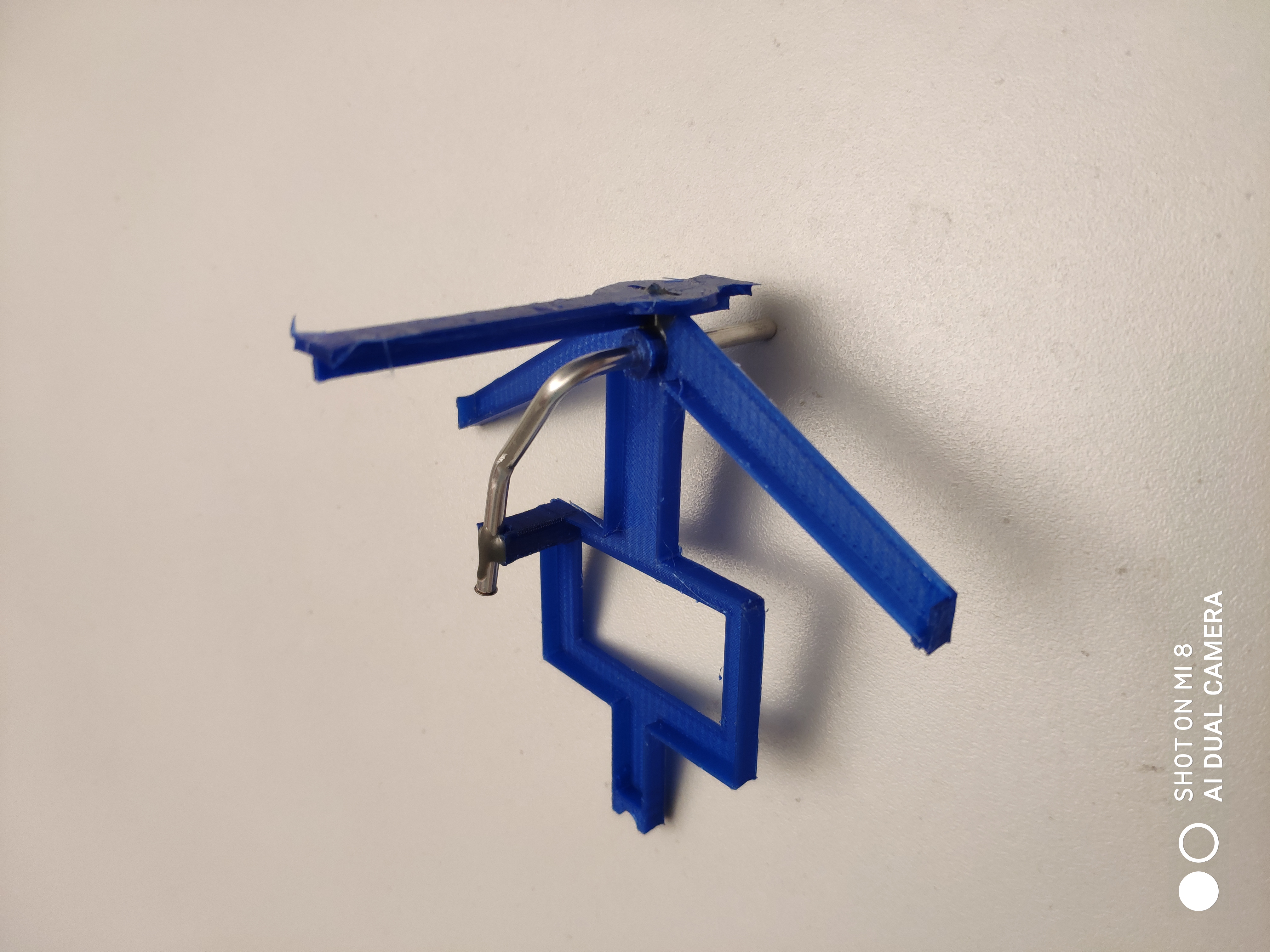 Accuhalterung und Sheetführung
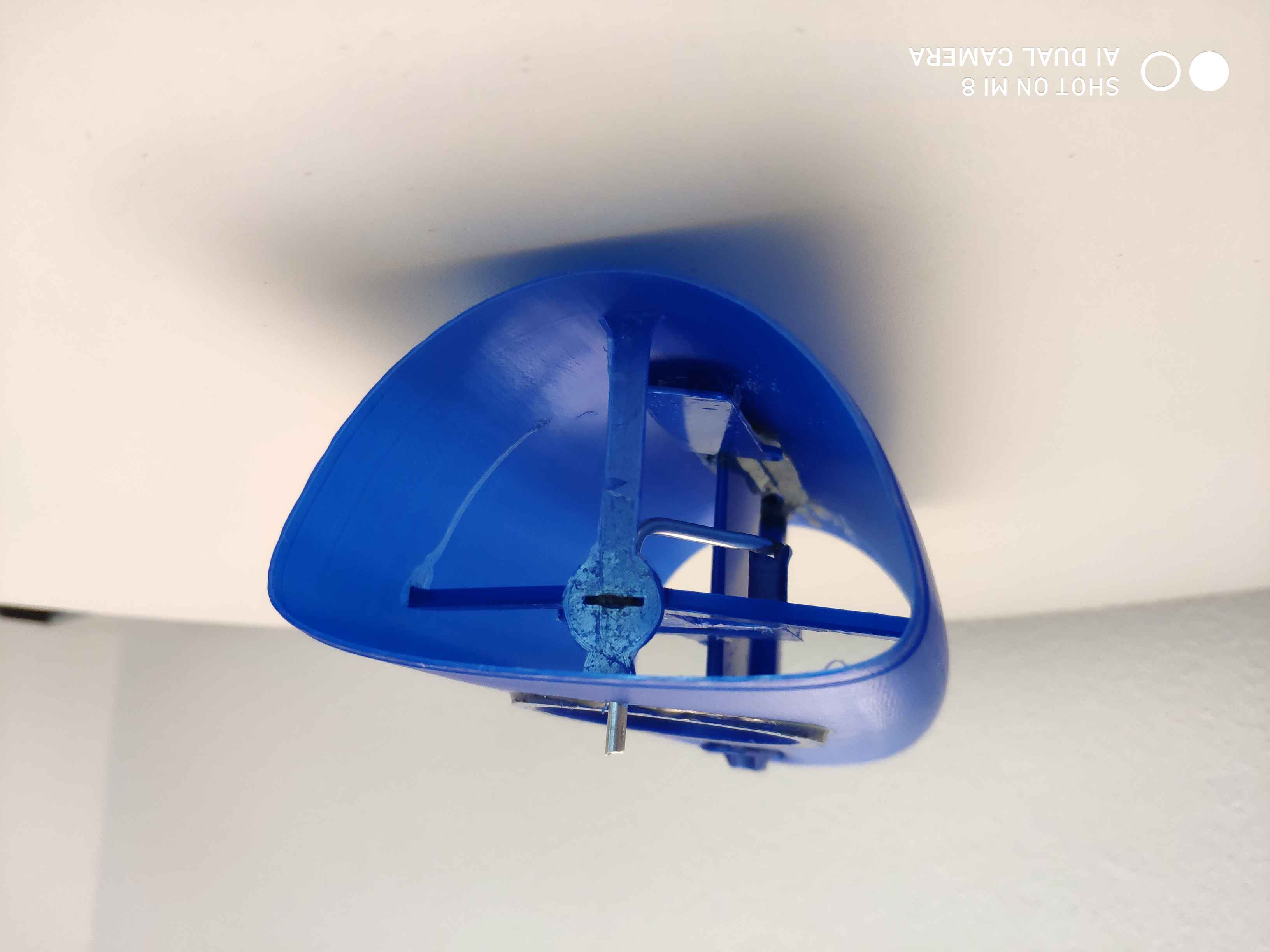


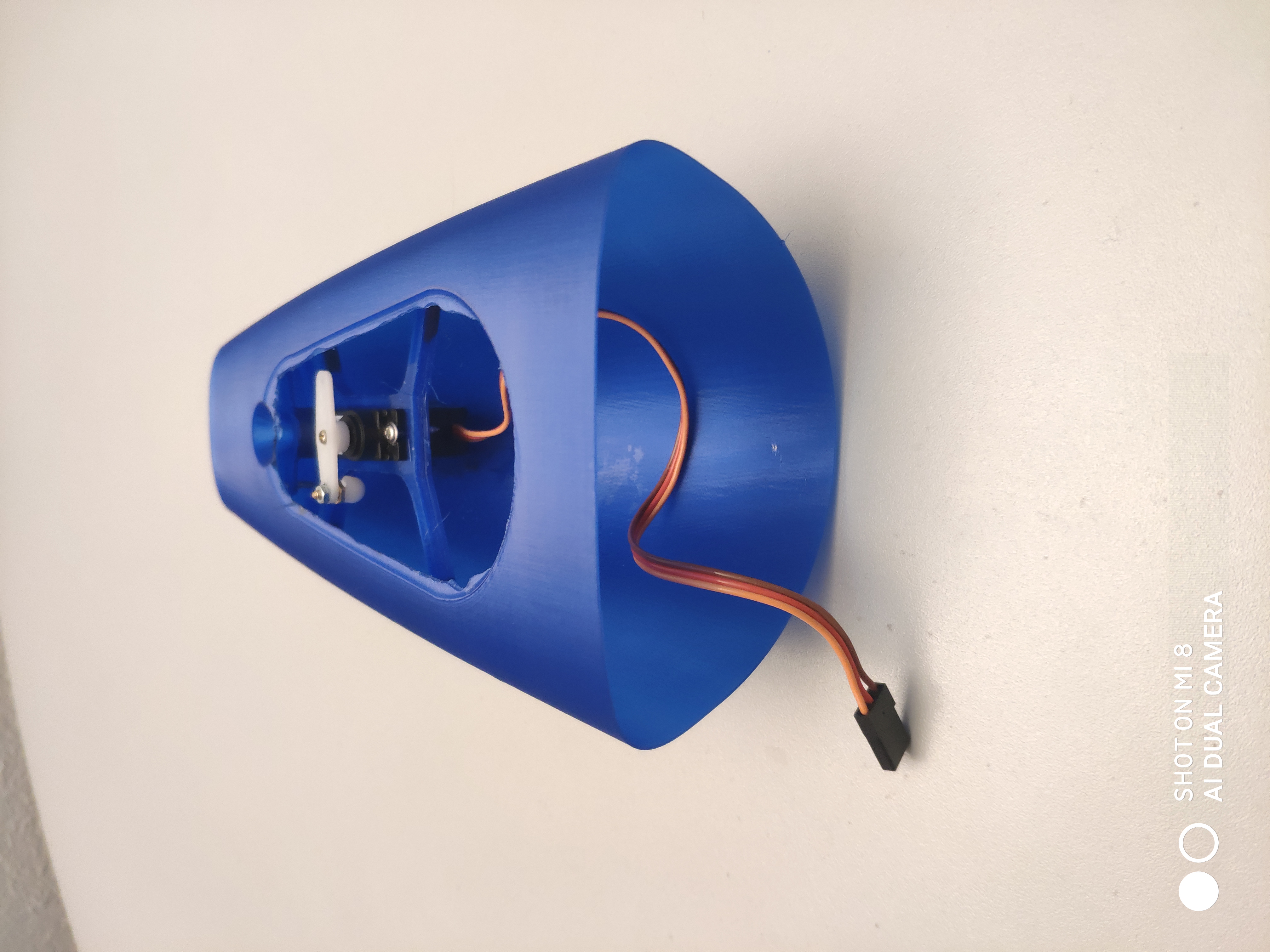 Heckteil mit Ruderkoker komplett verklebt!