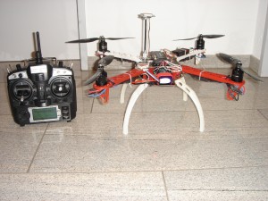
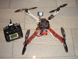
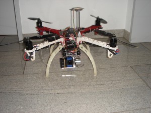
Hardware
- Motoren: 4x HP2212 1000KV Außenläufer, Brushless
- Propeller: Carbon 9 x 4.7″ CW/CCW
- Motorregler: 4x NFS ESC 30A Multirotor ESC SimonK Firmware (Opto)
- LiPo: Turnigy nano-tech 2200mah 3S 25~50C
- Batterie Buzzer 1S-8S Volttester
- Sensoren: GPS u-Blox CN-06 GPS Empfänger V3.0
- Flugcontroller: Ardupilot APM 2.5.2 mit 3 Achsen Gyro, Altimeter und Kompass
- Chassis: GFK rot/weiss mit integrierter PCB Platten
- 2 Achsen Gimbal für Kamerahalterung
- 2 Servomotoren
- Abmessungen: ca. 450x450mm
- Gewicht: 1200 g
- Schub: Rechnerisch bis zu 2400g gesamt bei 12A/Motor
- Sender: Turnigy 9X / FRSKY DJT-JR
- Empfänger FRSKY D8R-II Plus – 8 Kanal Empfänger m/ telemetry
- Div. Kabel und Steckverbindungen
Zielsetzung
Einen Quadrocopter entwickeln und bauen, der möglichst stabil fliegt und genügend Reserven besitzt um auch Nutzlasten wie HD Kameras etc. zu tragen.
Installing Mission Planner
Mission Planner is free, open source software available for Windows. These instructions will guide you through installing Mission Planner on your ground station computer.
Contents
Download the most recent Mission Planner installer file
Go to the Mission Planner download page and click on the “Mission Planner – MSI – Permanent link to latest” and then on the next page push the Download button. Alternatively you can get the MSI directly from this link.
Mandatory Hardware Configuration
As part of first time setup, you’ll need to configure some required hardware components using the Mission Planner. These instructions describe the process for selecting frame orientation and configuring the RC transmitter/receiver, compass, and accelerometer.
Contents
Because the next steps in this blog involve connecting to the Receiver, you need to turn off power to the ArduFlyer 2.5 board.
In Mission Planner, click Disconnect.
Disconnect the USB cable from ArduFlyer 2.5
I need to correct an error above, it is 5V +/- 5%, NOT 10%
You use one 3 pin cable from one of the headers to connect 5v power and GND to the receiver thus the board supplies power to the receiver
It does NOT matter which channel you use a 3 wire cable on since all the channels on the board can supply power.
The third wire, the Signal wire on that channel connects that channel signal.
The rest of the channels you may use ONLY require the SIGNAL wire to be connected.
There is no need to have a GND and supply wire connected to every channel as that makes the wiring stiffer, cumbersome and more likely to transfer vibration between the receiver and the vibration isolated board.
I use a Spektrum radio so that is what I will be illustrating here, the same principle applies no matter which receiver type you may be using.
Single Signal wires from the first 7 channels connected the last channel which decided to use a 3 wire cable to supply power to the receiver has not been connected yet.
The channel assignment on the Input headers.
Channel 1 is nearest the Alive LED, the white cable in the photo above
Here is how the green bars should move for each channel:
- CH 1: Roll/Aileron
- CH 2: Pitch/Elevator
- CH 3: Throttle
- CH 4: Yaw/Rudder
- CH 5: Flight Mode Switch
– Radio Calibration –
Connect USB cable from PC to ArduFlyer 2.5 board
Your receiver must be BOUND to your Radio, refer to the instructions that came with your receiver and Radio to perform BINDING
Switch on Your Radio transmitter, check that the Receiver Bind light is turned ON, if not you have to bind the receiver to the radio.
Run Mission Planner
Select correct COM Port, make sure BAUD is set to 115200
Click on the ConfigurationTab
On the left Click on Radio Calibration TAB
Click on Calibrate Radio, read the message then click OK, read the message then click OK
Move each Joystick to all the 4 corners, operate all switches and sliders.
Ideally the range of movement should be between 1000 and 2000, if it is a long way from that you need to adjust your Radio Travel oe End Points, refer to the instructions that came with your Radio.
Check that the correct green bar moves for each joystick, if a different bar moves, that means you have your radio channel connection between the Receiver and ArduFlyer 2.5 connected incorrectly, switch your cables around to correct the situation.
Check that the green bars all move in the correct direction as detailed below
NOTE: Pitch is backward to the way you would expect it to be
Here is how the green bars should move for each channel:
- CH 1: Roll Left = low PWM – Roll Right = High PWM
- CH 2: Pitch Forward = low PWM – Pitch Back = High PWM
- CH 3: Low Throttle = low PWM – High Throttle = High PWM
- CH 4: Yaw Left = low PWM – Yaw Right = High PWM
- CH 5: Flight Mode
- CH 6: up to you
- CH 7: not engaged = low PWM – engaged = High PWM
When you are done click on Click when Done
Click OK
At this point there are no motors connected so it is safe to test how to arm motors and become familiar with how it operates.
NO MOTORS ARE CONNECTED
In Mission Planner, click on the Flight Data Tab
Electronic speed controllers are responsible for spinning the motors at the speed requested by the autopilot. Most ESCs need to be calibrated so that they know the minimum and maximum pwm values that the flight controller will send. This page provides instructions for calibrating ESCs. Please complete radio calibration before performing ESC calibration.
About ESC Calibration
ESC calibration will vary based on what brand of ESC you are using, so always refer to the documentation for the brand of ESC you are using for specific information (such as tones). “All at once” calibration works well for most ESCs, so it is good idea to attempt it first and if that fails try the “Manual ESC-by-ESC” method.
- For 3DR ESCs can use the “All at once” method.
- DJI Opto ESCs do not require and do not support calibration, so skip this page completely
- Some brands of ESC do not allow calibration and will not arm unless you adjust your radio’s throttle end-points so that the minimum throttle is around 1000 PWM. Note that if you change the end-points on your TX you must re-do the Radio Calibration.
- Begin this procedure only after you have completed the “Calibrate radio control” section of the Configuring Hardware page and “Connect ESCs and motors” part of the Assembly Instructions. Next follow these steps:
All at once calibration
Safety Check!
Before calibrating ESCs, please ensure that your copter has NO PROPS on it and that the APM is NOT CONNECTED to your computer via USB and the Lipo battery is disconnected.


- Turn on your transmitter and put the throttle stick at maximum.

- Connect the Lipo battery. The autopilot’s red, blue and yellow LEDs will light up in a cyclical pattern. This means the it’s ready to go into ESC calibration mode the next time you plug it in.

- With the transmitter throttle stick still high, disconnect and reconnect the battery.


- For PX4 or Pixhawk, press and hold the safety button until it displays solid red.
- The autopilot is now in ESC calibration mode. (On an APM you may notice the red and blue LEDs blinking alternatively on and off like a police car).
- Wait for your ESCs to emit the musical tone, the regular number of beeps indicating your battery’s cell count (i.e. 3 for 3S, 4 for 4S) and then an additional two beeps to indicate that the maximum throttle has been captured.
- Pull the transmitter’s throttle stick down to its minimum position.

- The ESCs should then emit a long tone indicating that the minimum throttle has been captured and the calibration is complete.
- If the long tone indicating successful calibration was heard, the ESCs are “live” now and if you raise the throttle a bit they should spin. Test that the motors spin by raising the throttle a bit and then lowering it again.
- Set the throttle to minimum and disconnect the battery to exit ESC-calibration mode.
-
Testing
Once you have calibrated your ESCs, you can test them by plugging in your LiPo. Remember: no propellers!
- Ensure your transmitter’s flight mode switch is set to “Stabilize Mode”.
- Arm your copter (instructions are (Here!) if you’ve never done this before)
- Give a small amount of throttle. All motors should spin at about same speed and they should start at the same time. If the motors do not all start at the same time and spin at the same speed, the ESC’s are still not properly calibrated.
- Disarm your copter
- Turn on your transmitter and put the throttle stick at maximum.
Live Calibration of offsets
Ohne LiPo! Nur USB!
- Push the “Live Calibration” button to start the calibration.
- A window will appear that shows a sphere (or two if your flight controller has two compasses) with a red dot showing where the compass is pointing. As you rotate the vehicle you will notice the red dot moves and (perhaps confusingly) the sphere itself also rotates. A colored trail is left behind wherever the compass has already been.
- On the sphere are six targets shown as white dots.
- Rotate the vehicle so that the red dot reaches each white dot and causes it to disappear.
- When all white dots are gone you can push Done to complete the calibration and save the offsets.
- The final offsets will be displayed (3 numbers for each compass), if all these numbers are below 250 then you can assume they are good. If you missed the numbers they can be seen as COMPASS_OFS_X, Y and Z in the Advanced Parmaeters list. If the numbers are very high it may indicate there is some metal near the compasses.
One strategy for capturing all the white dots is to rotate the vehicle slowly so that each side (front, back, left, right, top and bottom) points down toward the ground for a few seconds (Note: the image below shows only 4 of the 6 recommended positions)
The video below is from earlier versions of the calibration routine but may still produce good offsets.
-
- Kompassmot
http://copter.ardupilot.com/wiki/ac_compasssetupupadvanced/
Live Kalibrierung Kompass und unter Motoren!
CompassMot – compensation for interference from the power wires, ESCs and motors
This is recommended for vehicles that have only an internal compass and on vehicles where there is significant interference on the compass from the motors, power wires, etc. CompassMot only works well if you have a battery current monitor because the magnetic interference is linear with current drawn. It is technically possible to set-up CompassMot using throttle but this is not recommended.
Please follow these instructions:
- Enable the current monitor (aka Power Module)
- Disconnect your props, flip them over and rotate them one position around the frame. In this configuration they should push the copter down into the ground when the throttle is raised
- Secure the copter (perhaps with tape) so that it does not move
- Turn on your transmitter and keep throttle at zero
- Connect your vehicle’s Lipo battery
- Connect your flight controller to your computer with the usb cable
-
- If using AC3.1.5:
- open the Terminal screen, press the “Connect APM” or “Connect PX4″ button
- At the prompt type setup and then compassmot.
- If the PowerModule/Current monitor is enabled you should see “measuring compass vs CURRENT”
- You should hear your ESCs arming beep
- Raise the throttle slowly to between 50% ~ 75% (the props will spin!) for 5 ~ 10 seconds
- Quickly bring the throttle back down to zero
- Press the Finish button (AC3.2) or Press enter (AC3.1.5) to complete the calibration
- Check the % of interference displayed. If it is less than 30% then your compass interference is acceptable and you should see good Loiter, RTL and AUTO performance. If it is 31% ~ 60% then the interference is in the “grey zone” where it may be ok (some users are fine, some are not). If it is higher than 60% you should try moving your APM/PX further up and away from the sources of interference or consider purchasing an external compass or GPS+compass module.
Here is a video of the procedure based on AC3.1.5:
- If using AC3.1.5:
- Fly your copter in Loiter mode in at least two directions and ensure that after a fast forward flight you do not see any circling (also known as “toilet bowling”).
- If you find it’s impossible to tune away the circling then it’s likely your compass interference is will require an external compass or GPS+compass module.


